


Aim:
To 'fix' some of the major design and performance issues with the Nerf (Elite) Rayven, whilst impacting the appearance of the blaster as little as possible. Specifically the abysmal trigger pull and performance loss due to the 'barrel', plus some other minor issues. A motor replacement to pololu motors will also be performed.
Things To Note:
Many of these solutions have been adapted (or in some cases copied) from mods other people have performed upon their Rayvens. It would be pointless to list all the rayven mod guides I took inspiration or borrowed mods from, in short; if it's about improving the rayven's performance and on the internet; I read it and probably used part of it in this mod guide.
Finally, I performed this mod in a slightly different order, so some of the pictures may seem a little 'off' timescale-wise, the guide was put in this order to simply make it easier to read.
Materials:
1x Nerf Rayven or Nerf Elite Rayven
1x Century Spring Corp. C-25 utility extension spring
2x Pololu #611 high-powered motors
25mm UPVC thin-walled (grey) electrical conduit (could be substituted for 3/4" thinwalled PVC instead)
A dremel
A hot-glue gun
A soldering iron
Thick gauge wire (I used 3.8mm if memory serves)
Etape
Epoxy
Superglue
Solder
Hot-glue sticks
White lithium greese
Tools:
Dremel
Pipe Cutter
Various Screwdrivers
Various knives (I used a hobby scalpel and a swiss army knife)
Disassembly:
Remove all the shell screws and open it up. Nearly all the screws seem to be the same, if memory serves the two in the tactical rail are a little shorter than the other screws. Remove the tactical rail spring and holder bit and try not to lose it.
[

Also remove the clip guide piece and put it aside somewhere safe.


The clip release lever should also be removed and stored somewhere safe.


Original Circuit Removal:
The first thing to do is remove all the electrical circuitry, including all the electronic locks. The only electronic part in the blaster that will not be removed is the motor switch located under the trigger. To remove the electronic components all you have to do is make the following cuts (I just used a pair of scissors):


Now all you have to do is yank out the wiring:


These components can be thrown into your electronics scrap box:

Manual Lock Removal:
With the electronic locks removed only the two manual locks remain, the first one stops you from being able to pull the trigger whilst the flywheels aren't spinning, which is a good thing; So I left the first lock alone. The second lock, which is much less practical, stops you from being able to pull the trigger whilst no clip is loaded, and was easily removed with just a screwdriver:


These components, again, go to the scrap box:

Fixing the Trigger:
The first thing you need to do is mark the part of the shell, where the wire ('connecter wire') that connects the trigger to the dart pusher, passes under the flywheels. It's probably easier to see in the picture below. Then use a knife or scalpel or even a dremel to cut out a chunk of the shell at this spot. This is done because whenever you pull the trigger the 'connecter wire' rubs on this part of the shell causing friction and making the trigger pull slightly harder.


Remove the dart-pusher from the shell. You do this by separating it from the trigger (a single screw connects them) and removing the plate that covers the dart pusher and forms part of the mag-well.


Next take the dart-pusher and slide the compression spring on it off; the spring can go into the scrap box. Lubricate the dart-pusher with some white lithium grease and put the dart pusher assembly back together (minus the extension spring).


Next you'll need to remove the 'flywheel assembly' and cut the shell as shown (I just used a knife, but a dremel would also work). Mine's a bit messy, but it's internal so it doesn't matter too much.


Now all you need to do is take your Century Spring Corp. C-25 utility extension spring and insert it as shown. It may seem odd to cut the shell to attach this spring, when there's a perfectly good screw-port nearby, but I experimented a bit and found this gave the smoothest trigger pull.


Replacing The Internal Barrel:
For this part of the mod you'll need the faux barrel pipe and outer barrel piece. In newer models of the rayven the outer barrel piece seems to be glued to one side of the shell, so I had to cut and dremel a bit to remove it from the shell, luckily the damaged parts were going to be cut off anyway.

Once you've got your barrel piece separated, put the barrel tube aside and take your outer barrel piece. You're going to mark and cut the piece as shown, this is to allow a new wider barrel to be run through the outer barrel piece. You'll also have to grind out a ridge on the inside of the outer barrel piece.


Next get the faux barrel pipe, insert it into the blaster as shown and mark off where it protrudes from the flywheel assembly.

Now remove the faux barrel pipe, measure a further 20mm from the first mark and cut off a small 'nub' of the pipe.

Wrap one end of the 'nub' of faux barrel pipe in etape until it will fit snuggly into your new barrel material (about 300mm of 25mm thin-walled UPVC pipe in my case).

Now, using epoxy glue, glue the 'nub' of faux barrel pipe into the new barrel leaving the originally marked off part of the faux barrel pipe protruding out from the new barrel.

Test-fit the new barrel to see if it can fit through the outer barrel piece.

Next we'll have to make a few shell modifications to accommodate the new barrel, these were done with a dremel with a sanding bit and have to be done to both sides of the shell.


Now test fit the new barrel into the blaster and mark off where it protrudes from the outer barrel piece. Remove the barrel and cut it to length.

Next wrap the end of the barrel in some etape until it fits snuggly into the outer barrel piece and use epoxy glue to glue it into the outer barrel piece.


Swapping The Motors:
In the interest of saving space and not cluttering this guide too much I'm not going to go into great detail how you take the old motors out of their housing and insert the new ones, mostly because it's very simple, but very long and tedious to explain. All the pictures for this part are available on my photobucket account, so you can go there to see all the pictures if you wish, but the gist of it is; This is what it looks like to begin with:

This is what I should look like after:

And these are scrap bin pieces:

Fixing The Clip Alignment:
After reading a bunch of other Rayven mods and doing a few experiments of my own I learned that the rayven mag-well is not particularly well designed. Several people have noted that the magazine does not sit in the centre of the mag-well, but rather slightly to one side, causing problems when the darts enter the flywheels. An additional problem that I noticed whilst playing around with this is that elite clips don't seem to properly load into the mag-well. They don't seem to activate the clip release lever that holds the clips in place. The best way I've seen to fix these issues was done by torukmakto4 over at Nerf Mods and Reviews.
Basically his solution was to glue a piece of plastic to part of the shell in the mag-well on an angle (this is the opposite shell half to the one we've been working on most of the guide). Basically this piece corresponds to a nub of plastic on the top of the nerf clips and acts as a ramp that centres the clip. I superglued a small piece of 1mm thick plasticard, but any other plastic will do.


After the piece was glued in place I reinforced it with a large amount of hot glue. This seemed to fix both the centring and elite clip issues.

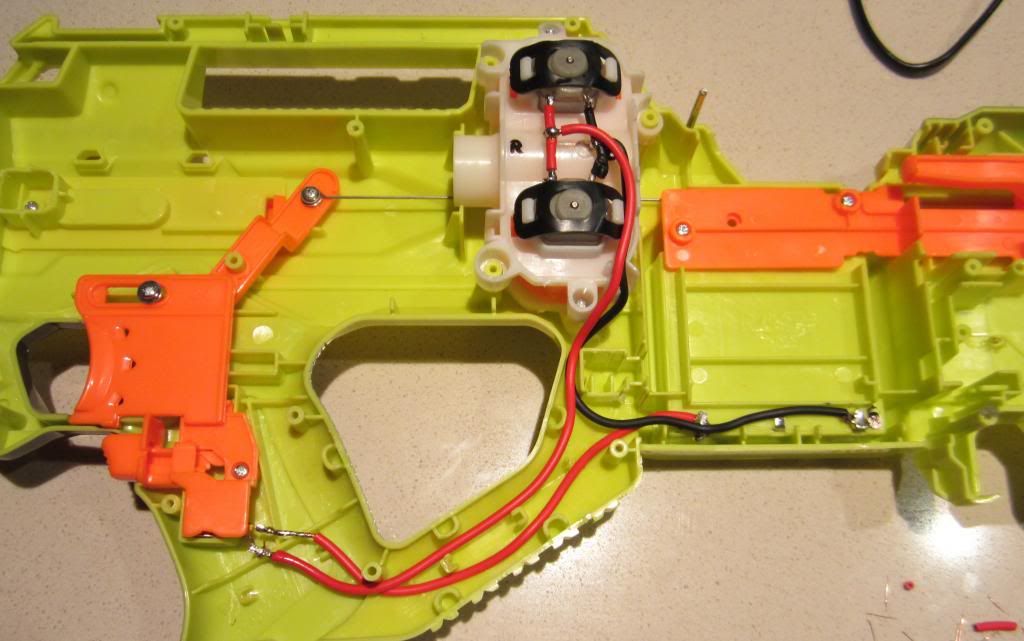
The New Replacement Circuit:
Again in the interest of space I'll Just put up this single image of my circuit. I feel it explains how and where everything is connected better than I ever could with text. As long as all your wires lead to the same things as mine you're good to go. As a note I did use etape to cover exposed joins, I just don't have a picture of it, but it is certainly important to eliminate the chance of short-circuits.
At this stage the blaster is all finished. Close it up and you're good to go.

Performance:
With all these fixes finished you end up with a blaster that has the same performance as an equally modded stryfe. The ranges are good and the trigger pull is smooth and easy.
That is all.
To 'fix' some of the major design and performance issues with the Nerf (Elite) Rayven, whilst impacting the appearance of the blaster as little as possible. Specifically the abysmal trigger pull and performance loss due to the 'barrel', plus some other minor issues. A motor replacement to pololu motors will also be performed.
Things To Note:
Many of these solutions have been adapted (or in some cases copied) from mods other people have performed upon their Rayvens. It would be pointless to list all the rayven mod guides I took inspiration or borrowed mods from, in short; if it's about improving the rayven's performance and on the internet; I read it and probably used part of it in this mod guide.
Finally, I performed this mod in a slightly different order, so some of the pictures may seem a little 'off' timescale-wise, the guide was put in this order to simply make it easier to read.
Materials:
1x Nerf Rayven or Nerf Elite Rayven
1x Century Spring Corp. C-25 utility extension spring
2x Pololu #611 high-powered motors
25mm UPVC thin-walled (grey) electrical conduit (could be substituted for 3/4" thinwalled PVC instead)
A dremel
A hot-glue gun
A soldering iron
Thick gauge wire (I used 3.8mm if memory serves)
Etape
Epoxy
Superglue
Solder
Hot-glue sticks
White lithium greese
Tools:
Dremel
Pipe Cutter
Various Screwdrivers
Various knives (I used a hobby scalpel and a swiss army knife)
Disassembly:
Remove all the shell screws and open it up. Nearly all the screws seem to be the same, if memory serves the two in the tactical rail are a little shorter than the other screws. Remove the tactical rail spring and holder bit and try not to lose it.
[


Also remove the clip guide piece and put it aside somewhere safe.


The clip release lever should also be removed and stored somewhere safe.


Original Circuit Removal:
The first thing to do is remove all the electrical circuitry, including all the electronic locks. The only electronic part in the blaster that will not be removed is the motor switch located under the trigger. To remove the electronic components all you have to do is make the following cuts (I just used a pair of scissors):


Now all you have to do is yank out the wiring:


These components can be thrown into your electronics scrap box:

Manual Lock Removal:
With the electronic locks removed only the two manual locks remain, the first one stops you from being able to pull the trigger whilst the flywheels aren't spinning, which is a good thing; So I left the first lock alone. The second lock, which is much less practical, stops you from being able to pull the trigger whilst no clip is loaded, and was easily removed with just a screwdriver:


These components, again, go to the scrap box:

Fixing the Trigger:
The first thing you need to do is mark the part of the shell, where the wire ('connecter wire') that connects the trigger to the dart pusher, passes under the flywheels. It's probably easier to see in the picture below. Then use a knife or scalpel or even a dremel to cut out a chunk of the shell at this spot. This is done because whenever you pull the trigger the 'connecter wire' rubs on this part of the shell causing friction and making the trigger pull slightly harder.


Remove the dart-pusher from the shell. You do this by separating it from the trigger (a single screw connects them) and removing the plate that covers the dart pusher and forms part of the mag-well.


Next take the dart-pusher and slide the compression spring on it off; the spring can go into the scrap box. Lubricate the dart-pusher with some white lithium grease and put the dart pusher assembly back together (minus the extension spring).


Next you'll need to remove the 'flywheel assembly' and cut the shell as shown (I just used a knife, but a dremel would also work). Mine's a bit messy, but it's internal so it doesn't matter too much.


Now all you need to do is take your Century Spring Corp. C-25 utility extension spring and insert it as shown. It may seem odd to cut the shell to attach this spring, when there's a perfectly good screw-port nearby, but I experimented a bit and found this gave the smoothest trigger pull.


Replacing The Internal Barrel:
For this part of the mod you'll need the faux barrel pipe and outer barrel piece. In newer models of the rayven the outer barrel piece seems to be glued to one side of the shell, so I had to cut and dremel a bit to remove it from the shell, luckily the damaged parts were going to be cut off anyway.

Once you've got your barrel piece separated, put the barrel tube aside and take your outer barrel piece. You're going to mark and cut the piece as shown, this is to allow a new wider barrel to be run through the outer barrel piece. You'll also have to grind out a ridge on the inside of the outer barrel piece.


Next get the faux barrel pipe, insert it into the blaster as shown and mark off where it protrudes from the flywheel assembly.

Now remove the faux barrel pipe, measure a further 20mm from the first mark and cut off a small 'nub' of the pipe.

Wrap one end of the 'nub' of faux barrel pipe in etape until it will fit snuggly into your new barrel material (about 300mm of 25mm thin-walled UPVC pipe in my case).

Now, using epoxy glue, glue the 'nub' of faux barrel pipe into the new barrel leaving the originally marked off part of the faux barrel pipe protruding out from the new barrel.

Test-fit the new barrel to see if it can fit through the outer barrel piece.

Next we'll have to make a few shell modifications to accommodate the new barrel, these were done with a dremel with a sanding bit and have to be done to both sides of the shell.


Now test fit the new barrel into the blaster and mark off where it protrudes from the outer barrel piece. Remove the barrel and cut it to length.

Next wrap the end of the barrel in some etape until it fits snuggly into the outer barrel piece and use epoxy glue to glue it into the outer barrel piece.


Swapping The Motors:
In the interest of saving space and not cluttering this guide too much I'm not going to go into great detail how you take the old motors out of their housing and insert the new ones, mostly because it's very simple, but very long and tedious to explain. All the pictures for this part are available on my photobucket account, so you can go there to see all the pictures if you wish, but the gist of it is; This is what it looks like to begin with:

This is what I should look like after:

And these are scrap bin pieces:

Fixing The Clip Alignment:
After reading a bunch of other Rayven mods and doing a few experiments of my own I learned that the rayven mag-well is not particularly well designed. Several people have noted that the magazine does not sit in the centre of the mag-well, but rather slightly to one side, causing problems when the darts enter the flywheels. An additional problem that I noticed whilst playing around with this is that elite clips don't seem to properly load into the mag-well. They don't seem to activate the clip release lever that holds the clips in place. The best way I've seen to fix these issues was done by torukmakto4 over at Nerf Mods and Reviews.
Basically his solution was to glue a piece of plastic to part of the shell in the mag-well on an angle (this is the opposite shell half to the one we've been working on most of the guide). Basically this piece corresponds to a nub of plastic on the top of the nerf clips and acts as a ramp that centres the clip. I superglued a small piece of 1mm thick plasticard, but any other plastic will do.


After the piece was glued in place I reinforced it with a large amount of hot glue. This seemed to fix both the centring and elite clip issues.

The New Replacement Circuit:
Again in the interest of space I'll Just put up this single image of my circuit. I feel it explains how and where everything is connected better than I ever could with text. As long as all your wires lead to the same things as mine you're good to go. As a note I did use etape to cover exposed joins, I just don't have a picture of it, but it is certainly important to eliminate the chance of short-circuits.

At this stage the blaster is all finished. Close it up and you're good to go.

Performance:
With all these fixes finished you end up with a blaster that has the same performance as an equally modded stryfe. The ranges are good and the trigger pull is smooth and easy.
That is all.

