Good evening boys and girls! Today we'll be running through a safety removal and voltage upgrade on the newly released Nerf Stryfe.
___________________________________________________________________________
Tools and Materials Required
Phillips head screwdriver
Soldering iron and solder
Wire strippers
Electrical tape/heat shrink
___________________________________________________________________________
Allright, go time!

We'll start by removing all the screws from the shell.

There are two different sized screws in the shell which we'll need to remember when we come back to reassembly.

There are two of the smaller screws and they both go here.

Ok, once we're inside take a moment or two to try and get an understanding of the internals and how they work. It will help with reassembly to no end.


Cool, lets get back to it. Start by removing the screw that holds the trigger lever in place.

Which will then let us remove the whole dart pusher assembly.

Then remove the jam door.

Then the trigger. It's held in place by this screw.

Bam! and the trigger is gone...

This is the first safety that we'll be removing today. It checks that there's a clip in the blaster and will cut power to the motors if there isn't. I don't want that feature so it goes.

Once we remove the cover we'll find the micro switch. Remove the orange bits here.

Like so.

Then we'll move to the top of the blaster and examine the dart checker safety thing. This little orange piece here checks that there's a dart in the clip and won't let you pull the trigger without one.

Clip in, no dart = dart checker down

Clip in, with dart = dart checker up.

With the dart checker down (and the dart pusher back in for the sake of the photo) we can see how it blocks the dart pusher.

While when it's up we can see that it clears. Understand? Cool.

So to get around the dart checker, we're just going to plain old remove it. Even if you do no other mods from this guide, I'd strongly recommend removing it. Many people have reported issues with non-elite clips not triggering the dart pusher so let's just remove that whole possibility.

Next up we'll remove the microswitch that checks if the jam door is closed. We don't need that either.

Now at this point we should have two microswitches floating in the shell. We need to bypass these.

To do this we'll start by de-soldering both the orange and blue wires from the bottom switch.


The top switch is a little more complicated. It has two negative inputs, one form the trigger and one direct from the battery, and one output. In absolution it's essentially just a switch on the negative wire between the battery and the motor.

Pull the heat shrink back.

Desolder the red wire.

Then solder it to to the blue wire we removed from the other switch we removed earlier.

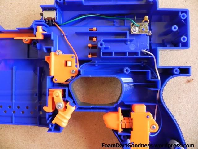
Now let's move to the thermistor. I apparently forgot to take a photo at this point but if we refer back to a photo from the start...

We'll see that it's held in by a screw. Remove that.
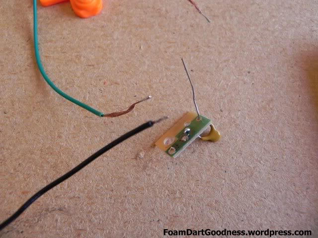
The thermistor is a component that apparently seems to confuse a lot of people but it's a really simply component. Essentially the more voltage you run through it, the hotter it gets; the hotter it gets, the higher resistance it provides. For us this means that once it reaches a certain temperature it cuts power to the motors. This particular thermistor will cut power after a few minutes of use at 9v, or almost instantly at 16v. Because we want to increase the voltage, we have to remove it.
To do this simply desolder the black wire from the thermistor and solder it directly to the negative terminal on the battery.

Also, good point to mention that we taped the red/blue connection we made earlier. Heat shrink would be better but I'm lazy.

That's about it folks; time for reassembly!

First, the dart pusher and spring. One screw to hold it in and we need to slip the spring over the post at the end.

Then the trigger.

Then the jam door.

Then the other half of the shell.

Ok, not quite done; we still need to up the voltage. I've been tossing up between three trustfires and one dummy, or two trustfires and two dummies, and I'm honestly not sure what I prefer yet. Three batteries is obviously more powerful, but it's less accurate and makes a stupider noise. I don't know...

Which ever way you choose to power your Stryfe though, you should still be pretty happy with it.
___________________________________________________________________________
Tools and Materials Required
Phillips head screwdriver
Soldering iron and solder
Wire strippers
Electrical tape/heat shrink
___________________________________________________________________________
Allright, go time!

We'll start by removing all the screws from the shell.

There are two different sized screws in the shell which we'll need to remember when we come back to reassembly.

There are two of the smaller screws and they both go here.

Ok, once we're inside take a moment or two to try and get an understanding of the internals and how they work. It will help with reassembly to no end.


Cool, lets get back to it. Start by removing the screw that holds the trigger lever in place.

Which will then let us remove the whole dart pusher assembly.

Then remove the jam door.

Then the trigger. It's held in place by this screw.

Bam! and the trigger is gone...

This is the first safety that we'll be removing today. It checks that there's a clip in the blaster and will cut power to the motors if there isn't. I don't want that feature so it goes.

Once we remove the cover we'll find the micro switch. Remove the orange bits here.

Like so.

Then we'll move to the top of the blaster and examine the dart checker safety thing. This little orange piece here checks that there's a dart in the clip and won't let you pull the trigger without one.

Clip in, no dart = dart checker down

Clip in, with dart = dart checker up.

With the dart checker down (and the dart pusher back in for the sake of the photo) we can see how it blocks the dart pusher.

While when it's up we can see that it clears. Understand? Cool.

So to get around the dart checker, we're just going to plain old remove it. Even if you do no other mods from this guide, I'd strongly recommend removing it. Many people have reported issues with non-elite clips not triggering the dart pusher so let's just remove that whole possibility.

Next up we'll remove the microswitch that checks if the jam door is closed. We don't need that either.

Now at this point we should have two microswitches floating in the shell. We need to bypass these.

To do this we'll start by de-soldering both the orange and blue wires from the bottom switch.


The top switch is a little more complicated. It has two negative inputs, one form the trigger and one direct from the battery, and one output. In absolution it's essentially just a switch on the negative wire between the battery and the motor.

Pull the heat shrink back.

Desolder the red wire.

Then solder it to to the blue wire we removed from the other switch we removed earlier.

Now let's move to the thermistor. I apparently forgot to take a photo at this point but if we refer back to a photo from the start...

We'll see that it's held in by a screw. Remove that.
The thermistor is a component that apparently seems to confuse a lot of people but it's a really simply component. Essentially the more voltage you run through it, the hotter it gets; the hotter it gets, the higher resistance it provides. For us this means that once it reaches a certain temperature it cuts power to the motors. This particular thermistor will cut power after a few minutes of use at 9v, or almost instantly at 16v. Because we want to increase the voltage, we have to remove it.
To do this simply desolder the black wire from the thermistor and solder it directly to the negative terminal on the battery.

Also, good point to mention that we taped the red/blue connection we made earlier. Heat shrink would be better but I'm lazy.

That's about it folks; time for reassembly!

First, the dart pusher and spring. One screw to hold it in and we need to slip the spring over the post at the end.

Then the trigger.

Then the jam door.

Then the other half of the shell.

Ok, not quite done; we still need to up the voltage. I've been tossing up between three trustfires and one dummy, or two trustfires and two dummies, and I'm honestly not sure what I prefer yet. Three batteries is obviously more powerful, but it's less accurate and makes a stupider noise. I don't know...

Which ever way you choose to power your Stryfe though, you should still be pretty happy with it.


