I am unsure if this topic is even in the right section, so any moderators please move if necessary.
DISCLAIMER: This is NOT designed to be accurate or particularly useful for that matter and depending on the user-sourced components and modder build skill the effectiveness/outcome can be different to mine.
Some time ago I posted a topic regarding if anyone had been able to obtain a airsoft replica/fake LAM for use with Nerf, unfortunately after some heavy research I concluded that getting a pre-made functional LAM into Australia would be pretty much impossible due to our import laws.
The illegal part of the LAM is quite obviously the laser. You cannot import any laser module/device into Australia over 3mW, but anyone in oz CAN buy any laser 3mW and above from any Dick-Smith store without problems.... go figure.
I decided that the only way I could get a cool-looking moderately functional LAM was to build it myself.
An empty box that looks like a PEQ-15 LAM can be bought easily on ebay for $15-20ish. The particular one I bought was EXACTLY the same as their fully-functional model with some bits glued in place and other bits inside hacked off so that an airsoft battery can fit.
Due to the partially butchered insides I could not easily make the dial switch and push-button functional so for this build I decided to use a simple small off/on switch for the laser and a momentary 'remote' button for the flashlight.
Other than the outer box/housing, the additional components that I needed are as follows.
* Sharpie Permanent marker.
* Flashlight momentary remote + tail-cap (cheap knockoff from ebay).
* Laser module, <3mW if imported (I didn't really want it more powerful anyway).
* 5mm White CREE LED + appropriate resistor.
* Mono (or stereo doesn't matter) plug and socket.
* Small on/off switch
* Battery connecter for 9V (or whatever if using AA/AAA)
Any appropriate tools necessary INCLUDING soldering iron.
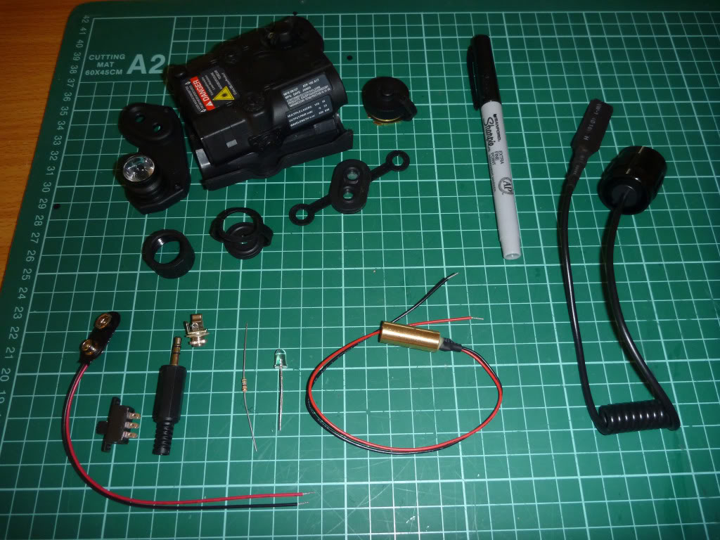
Here I have displayed out all the part I will be using. The small brass-colored cylinder with the wires out the back is the actual lase-module.
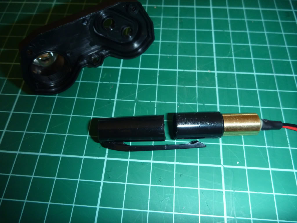
This is the useful function of the Sharpie marker, or more precisely the CAP of the marker. I actually found out that is was the perfect fit for the laser module! Just a tight enough fit so that it would not fall out. I only cit off the length that I needed.
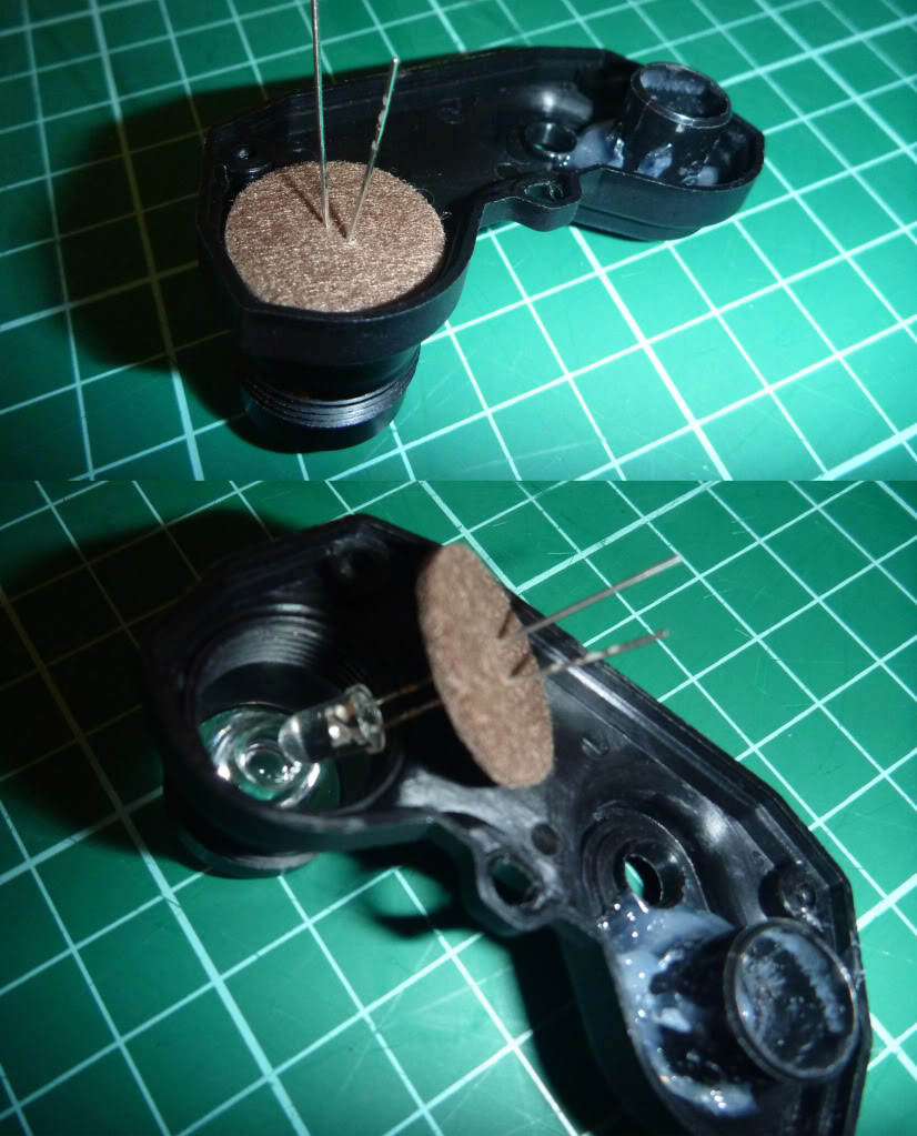
Here is the front of the LAM case showing how I glued the sharpie lid bit I cut off (first unsuccessfully with silicone then after I took these pics I glued if properly with epoxy and hot-glue) and how I used one of those small sticky felt pads to hold the LED in place.
Thankfully the LAM case still had its lens diffuser thing which the 5mm LED fit in perfect.
If anyone is worried about my use of the felt pad close to the CREE, don't worry this particular LED does not heat up like some of the more powerful ones.
NOTE: Depending on how neat you cut and glued the sharpie cap the laser may or may not go exactly straight. BE CAREFUL if you want it sorta accurate!
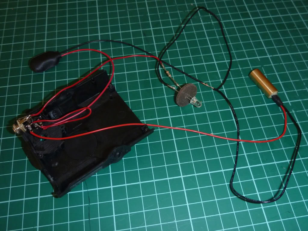
This is the completed circuit after soldering. REMEMBER to ALWAYS use a resistor before the LED or you could blow the LED.
With this circuit the power from the 9V battery goes both to the LED and the Laser module but first after going through the Headphone jack plug to turn on the LED, and the on/off switch for the Laser module.
This way I can leave the laser on and only turn on the light when necessary.
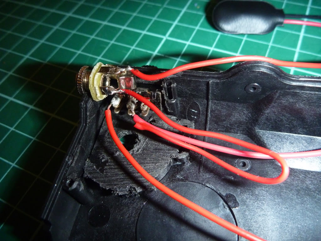
This picture shows a close up of the switch, socket and wiring. Before I closed the whole thing up I did use electrical tape to make sure everything could not short out.
Unfortunately I forgot to take any photos when I was cutting out the hole for the on/off switch to go (for the laser) which turned out to be the most difficult part of the whole thing.
I wanted to find a location that didn't look out-of-place or ugly but still be functional. The only real location was a small recess that is suppose to store a screw (try Google for a better description, lol).
The big problem was that this recess was VERY close to the hole where the headphone jack is supposed to go, so I had to Dremel and file and drill until the switch fit.
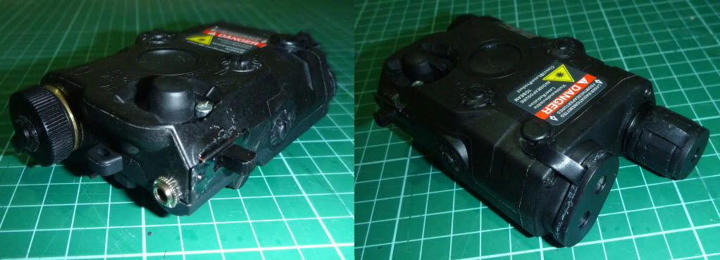
Here is the completed unit with everything stuffed (carefully!) in the case. I packed the 9V with felt and electrical tape to prevent possible shorting out when fit inside.
Below is a pic of the unit with both the LED and Laser on.

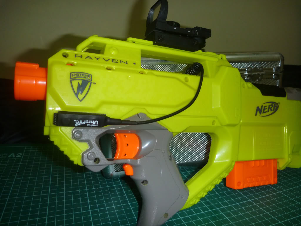
The following photos show how I mounted it to the side of my 9V Rayven. The Nerf rail DID need to be modified for the LAM to be mounted securely, I may post a pic later on how exactly I altered the rail depending if anyone would like to see.
You can also see in the pictures where I decided to put the LED remote button, I stuck the button on the shell with good outdoors double-sided tape.

I'm sorry if this may seem like is id not really detailed enough but most of the issues really depend of what component you use and where/how you decide to mount everything.
DISCLAIMER: This is NOT designed to be accurate or particularly useful for that matter and depending on the user-sourced components and modder build skill the effectiveness/outcome can be different to mine.
Some time ago I posted a topic regarding if anyone had been able to obtain a airsoft replica/fake LAM for use with Nerf, unfortunately after some heavy research I concluded that getting a pre-made functional LAM into Australia would be pretty much impossible due to our import laws.
The illegal part of the LAM is quite obviously the laser. You cannot import any laser module/device into Australia over 3mW, but anyone in oz CAN buy any laser 3mW and above from any Dick-Smith store without problems.... go figure.
I decided that the only way I could get a cool-looking moderately functional LAM was to build it myself.
An empty box that looks like a PEQ-15 LAM can be bought easily on ebay for $15-20ish. The particular one I bought was EXACTLY the same as their fully-functional model with some bits glued in place and other bits inside hacked off so that an airsoft battery can fit.
Due to the partially butchered insides I could not easily make the dial switch and push-button functional so for this build I decided to use a simple small off/on switch for the laser and a momentary 'remote' button for the flashlight.
Other than the outer box/housing, the additional components that I needed are as follows.
* Sharpie Permanent marker.
* Flashlight momentary remote + tail-cap (cheap knockoff from ebay).
* Laser module, <3mW if imported (I didn't really want it more powerful anyway).
* 5mm White CREE LED + appropriate resistor.
* Mono (or stereo doesn't matter) plug and socket.
* Small on/off switch
* Battery connecter for 9V (or whatever if using AA/AAA)
Any appropriate tools necessary INCLUDING soldering iron.

Here I have displayed out all the part I will be using. The small brass-colored cylinder with the wires out the back is the actual lase-module.

This is the useful function of the Sharpie marker, or more precisely the CAP of the marker. I actually found out that is was the perfect fit for the laser module! Just a tight enough fit so that it would not fall out. I only cit off the length that I needed.

Here is the front of the LAM case showing how I glued the sharpie lid bit I cut off (first unsuccessfully with silicone then after I took these pics I glued if properly with epoxy and hot-glue) and how I used one of those small sticky felt pads to hold the LED in place.
Thankfully the LAM case still had its lens diffuser thing which the 5mm LED fit in perfect.
If anyone is worried about my use of the felt pad close to the CREE, don't worry this particular LED does not heat up like some of the more powerful ones.
NOTE: Depending on how neat you cut and glued the sharpie cap the laser may or may not go exactly straight. BE CAREFUL if you want it sorta accurate!

This is the completed circuit after soldering. REMEMBER to ALWAYS use a resistor before the LED or you could blow the LED.
With this circuit the power from the 9V battery goes both to the LED and the Laser module but first after going through the Headphone jack plug to turn on the LED, and the on/off switch for the Laser module.
This way I can leave the laser on and only turn on the light when necessary.

This picture shows a close up of the switch, socket and wiring. Before I closed the whole thing up I did use electrical tape to make sure everything could not short out.
Unfortunately I forgot to take any photos when I was cutting out the hole for the on/off switch to go (for the laser) which turned out to be the most difficult part of the whole thing.
I wanted to find a location that didn't look out-of-place or ugly but still be functional. The only real location was a small recess that is suppose to store a screw (try Google for a better description, lol).
The big problem was that this recess was VERY close to the hole where the headphone jack is supposed to go, so I had to Dremel and file and drill until the switch fit.

Here is the completed unit with everything stuffed (carefully!) in the case. I packed the 9V with felt and electrical tape to prevent possible shorting out when fit inside.
Below is a pic of the unit with both the LED and Laser on.

The following photos show how I mounted it to the side of my 9V Rayven. The Nerf rail DID need to be modified for the LAM to be mounted securely, I may post a pic later on how exactly I altered the rail depending if anyone would like to see.
You can also see in the pictures where I decided to put the LED remote button, I stuck the button on the shell with good outdoors double-sided tape.


I'm sorry if this may seem like is id not really detailed enough but most of the issues really depend of what component you use and where/how you decide to mount everything.


