Hi guys,
Had 2 Stryfe's arrive from Amazon yesterday. Nice little sidearm, even for a flywheel. Fairly straightforward to mod, and rather rewarding.
Mod's covered -
* Lock removals
* Motor resistor removal
* Complete re-wire
* Voltage increase
* Installation of clicky switch
Tools:
•Basic tool kit
•Soldering iron
•Hot glue gun
•Digital Multimeter
Materials:
•Electrical Hook-up wire
•Unprotected 14500 li-ion batteries
•AA dummy spacer
•Forward Clicky switch
•Hot glue sticks, solder, heatshrink tubing etc
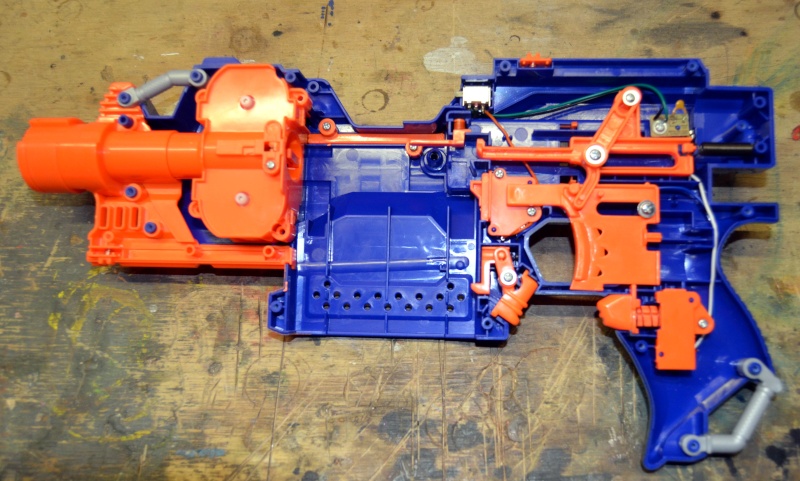
As always, start by opening up your blaster. There's no hidden screws, so this should be simple.
This is what you should see:

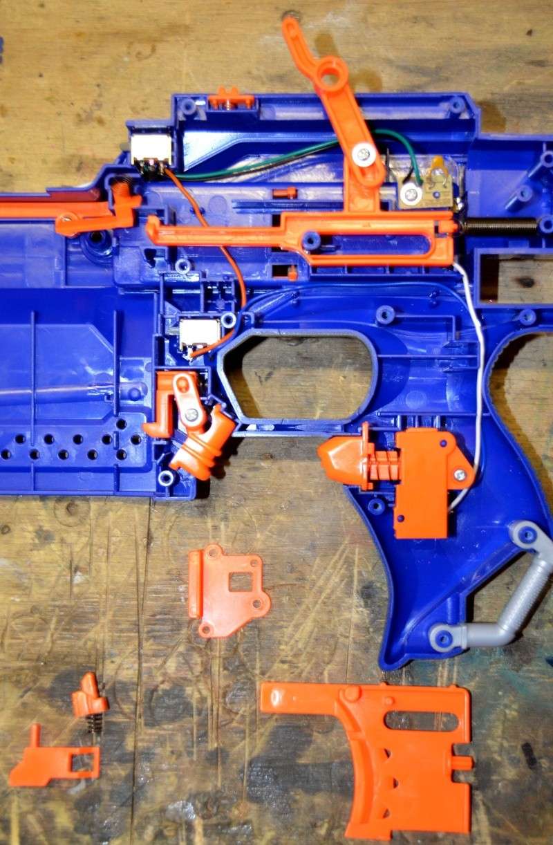
Close-up of internals:

First off, we'll remove the magazine lock. This enables the trigger to be pulled at any time, whether there's a clip loaded or not. Remove the screw for the lower connecting rod of the dart pusher, and the screw which holds the trigger in. Push the connecting rod out of the way, and remove the trigger. Now you have access to the mechanical trigger lock. Remove the two screws and the cover plate, and discard the two orange pieces and the spring.

Next we'll remove the mechanical lock for the trigger. Probably not a necessary mod if you don't plan on replacing the stock interlock switch. Remove the screw from the cover plate, and discard the orange piece.

Now on to the dart lock removal. Removing this component allows you to pull the trigger even if a dart isn't loaded in to the clip. Simply remove the orange piece and spring, and you're done.

For this next step, I removed all the wiring and interlocks from the blaster, as well as the circuit board connected to the inside of the battery tray. I also cut the positive and negative wires from the battery terminals, and removed all solder. On that note, I removed all the factory solder from everything in this blaster. It's a bit pedantic, but at least I know there's quality solder joints on all my connections.
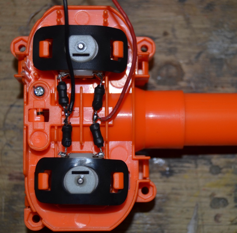
Remove the flywheel motor assembly, and turn over. You'll notice 4 resistors between the motors. Cut these resistor's out, and replace with wire (I just used some heavy duty LED tails). Obviously, take note of which is negative and positive prior to removing. Then, simply solder your hook-up wire to the two bridges.
BEFORE:

AFTER:

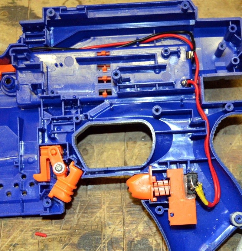
There's plenty of room to mount the clicky switch behind the acceleration trigger. I had to trim a minimal amount of plastic out for it to fit, and then secured in place with hot glue.

Wiring is pretty simple. Negative from battery terminal to motor. Positive from battery terminal to one side of the clicky switch, and then another positive wire from the other side of the switch to the motors to complete the circuit. I added a little heatshrink around the connections on the switch just to play it safe.
You'll also note that I cut the orange cover for the acceleration trigger interlock, so it would fit around the switch. Just made it look a little neater, and gave me some material to add a bit more hot glue to secure the switch in place so it won't move.

All internal components replaced.

These are all the pieces that I removed.

Add your preferred power supply, and check that everything works before closing up the blaster for testing.
I opted to use 3 x unprotected 14500 li-ion batt's, along with a AA dummy spacer. I've heard a few reports of burnt motors from 16.8 v, and running at 12.6 v hasn't caused me any issues so far - no burnt smell or thermal overload as of yet. Personally, with all the circuitry and resistors removed, running above 12.6 v will probably cause a major meltdown...
As a side-note, I added a small machine screw to the front of the dart pusher so it's compatible with stinger's. This isn't necessary with heavy sili tips or stock darts.
So, on to ranges. Firing flat (with a slight 5 degree elevation), I used 4 x 18rd Stampede clips, loaded with Elite darts, and 3 different weighted Stinger darts (0.8g, 1.0g, 1.2g). Longest distance was from a couple of elite darts which fishtailed madly. Shortest distance was from the heavier stingers. The most consistent range was from the 1.0g stinger darts, at approx 66 ft.
Min 51ft
Max 89ft
Avg 70ft
Mode 66ft
Cheers,
Had 2 Stryfe's arrive from Amazon yesterday. Nice little sidearm, even for a flywheel. Fairly straightforward to mod, and rather rewarding.
Mod's covered -
* Lock removals
* Motor resistor removal
* Complete re-wire
* Voltage increase
* Installation of clicky switch
Tools:
•Basic tool kit
•Soldering iron
•Hot glue gun
•Digital Multimeter
Materials:
•Electrical Hook-up wire
•Unprotected 14500 li-ion batteries
•AA dummy spacer
•Forward Clicky switch
•Hot glue sticks, solder, heatshrink tubing etc
As always, start by opening up your blaster. There's no hidden screws, so this should be simple.
This is what you should see:

Close-up of internals:

First off, we'll remove the magazine lock. This enables the trigger to be pulled at any time, whether there's a clip loaded or not. Remove the screw for the lower connecting rod of the dart pusher, and the screw which holds the trigger in. Push the connecting rod out of the way, and remove the trigger. Now you have access to the mechanical trigger lock. Remove the two screws and the cover plate, and discard the two orange pieces and the spring.

Next we'll remove the mechanical lock for the trigger. Probably not a necessary mod if you don't plan on replacing the stock interlock switch. Remove the screw from the cover plate, and discard the orange piece.

Now on to the dart lock removal. Removing this component allows you to pull the trigger even if a dart isn't loaded in to the clip. Simply remove the orange piece and spring, and you're done.

For this next step, I removed all the wiring and interlocks from the blaster, as well as the circuit board connected to the inside of the battery tray. I also cut the positive and negative wires from the battery terminals, and removed all solder. On that note, I removed all the factory solder from everything in this blaster. It's a bit pedantic, but at least I know there's quality solder joints on all my connections.
Remove the flywheel motor assembly, and turn over. You'll notice 4 resistors between the motors. Cut these resistor's out, and replace with wire (I just used some heavy duty LED tails). Obviously, take note of which is negative and positive prior to removing. Then, simply solder your hook-up wire to the two bridges.
BEFORE:

AFTER:

There's plenty of room to mount the clicky switch behind the acceleration trigger. I had to trim a minimal amount of plastic out for it to fit, and then secured in place with hot glue.

Wiring is pretty simple. Negative from battery terminal to motor. Positive from battery terminal to one side of the clicky switch, and then another positive wire from the other side of the switch to the motors to complete the circuit. I added a little heatshrink around the connections on the switch just to play it safe.
You'll also note that I cut the orange cover for the acceleration trigger interlock, so it would fit around the switch. Just made it look a little neater, and gave me some material to add a bit more hot glue to secure the switch in place so it won't move.

All internal components replaced.

These are all the pieces that I removed.

Add your preferred power supply, and check that everything works before closing up the blaster for testing.
I opted to use 3 x unprotected 14500 li-ion batt's, along with a AA dummy spacer. I've heard a few reports of burnt motors from 16.8 v, and running at 12.6 v hasn't caused me any issues so far - no burnt smell or thermal overload as of yet. Personally, with all the circuitry and resistors removed, running above 12.6 v will probably cause a major meltdown...
As a side-note, I added a small machine screw to the front of the dart pusher so it's compatible with stinger's. This isn't necessary with heavy sili tips or stock darts.
So, on to ranges. Firing flat (with a slight 5 degree elevation), I used 4 x 18rd Stampede clips, loaded with Elite darts, and 3 different weighted Stinger darts (0.8g, 1.0g, 1.2g). Longest distance was from a couple of elite darts which fishtailed madly. Shortest distance was from the heavier stingers. The most consistent range was from the 1.0g stinger darts, at approx 66 ft.
Min 51ft
Max 89ft
Avg 70ft
Mode 66ft
Cheers,


